Showing posts with label ESC. Show all posts

Sunday, December 23, 2018

Why most hobby grade BLDC out runners are actually permanent magnet synchronous motors (PMSM)

Look anywhere online for a brushless direct current (BLDC) electric motor and you will likely find something that looks like the out-runner shown below:
A hobby grade 'BLDC' motor
However, it turns out this is technically not a BLDC motor. By most definitions, it is actually a permanent magnet synchronous motor (PMSM). If you own a similar looking out-runner style hobby motor then you too may have a PMSM.

This post will briefly cover the difference between a BLDC motor and a PMSM and when this difference matters.

BLDC vs PMSM

BLDC and PMSM have a lot in common. Neither have brushes, both have permanent magnets on the rotor and have an armature on the stator. Where they differ is in how the magnetic field produced by the rotor magnets interacts with the windings of the armature.

Let's consider an 'out-runner' motor of the style shown below.
A cross-sectional view of a 6 slot, 8 pole (6N8P) motor
The movement of the rotor magnets past the stator teeth induces a back EMF (bEMF) into the windings of the armature. When the phase-phase bEMF is plotted with electrical angle (360 electrical degrees = 360 mechanical degrees / no. pole pairs) it may look sinusoidal, trapezoidal, or somewhere in between.


If a motor produces a trapezoidal bEMF then it is considered BLDC motor since this shape is similar to what would be seen from a conventional brushed DC motor. If your motor produces a sinusoidal bEMF then it is generally considered to be a PMSM. 

How to tell if your motor is a BLDC or PMSM? Measure its bEMF

If you have access to an oscilloscope then determining if your motor is a PMSM or a BLDC motor is as simple as measuring across any two phases and spinning the rotor to observe the bEMF shape. This can be done by hand for low kV motors or with the help of a power drill for high kV motors. After doing this for a 12 slot, 14 pole (12N14P) out-runner the following shape was seen:

Back EMF produced by a 12N14P out-runner
IMG_20180423_171938@0,5x.jpg
D5065 270 kV 12N14P brushless out-runner from Odrive Robotics
This motor clearly has a sinusoidal bEMF and so would be considered a PMSM. Repeating this same measurement for a couple of other motors from different manufacturers also yielded the same results.

A sinusoidal bEMF typically means a motor has been wound with distributed windings, where the windings are distributed over many slots, and is more common for large electric motors. Distributed windings are easily spotted by the overlap at the end of the motor.


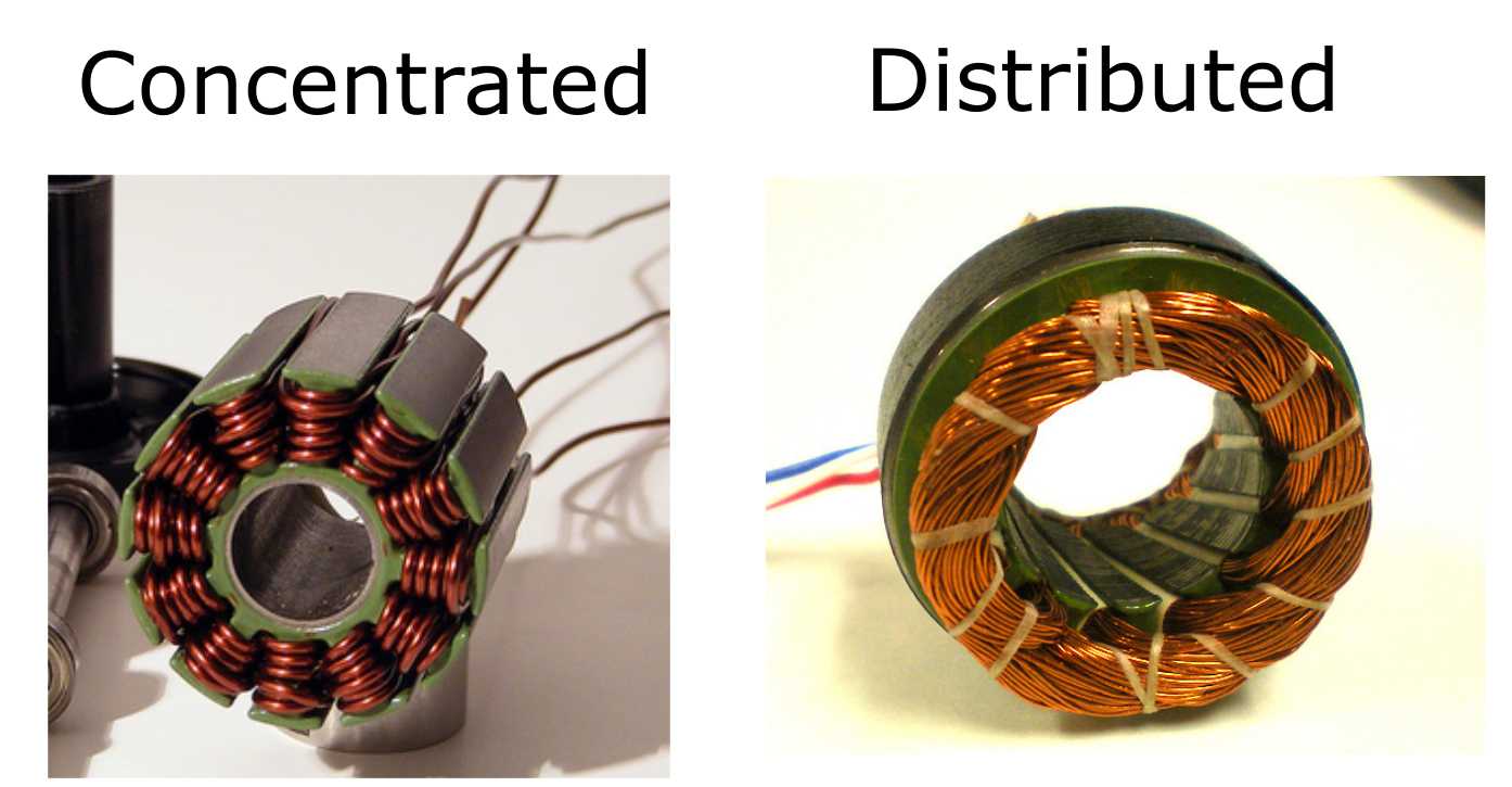
However, hobby grade brushless motors are almost universally constructed with concentrated windings. It is, therefore, a little surprising that they can produce a sinusoidal bEMF. The reason for a sinusoidal bEMF in the out-runner tested above is apparently related to its 12N14P configuration in combination with its doubly wound concentrated windings. I will explore this in more detail at some point in the future. Note that so far I have only measured 12N14P out-runner style motors and so you may see different results for motors with different slot/pole ratios or for in-runners.

BLDC or PMSM - Does it matter?

Useful torque is produced by an electric motor when you feed in a current waveform to each phase that perfectly opposes the a generated bEMF. Importantly, the shape of the waveform does not matter, so long as it exactly matches the bEMF waveform. For example, consider the torque produced by a PMSM and BLDC motor as seen by the figure below which were taken from James Mavey's excellent masters thesis.
Torque output vs current input for a PMSM (left) and a BLDC (right) motor
When you sum up the current contributions from each phase for the sinusoidal waveform (PMSM) and for the trapezoidal waveform (BLDC) you see the same result; a perfect constant output current, and therefore a constant output torque. Also, in theory at least, both motors should be equally efficient. In reality, even if you could perfectly match the current to the bEMF, the rapid change in flux density seen by the stator in a BLDC motor due to the use of a trapezoidal waveform is likely to induce larger eddy current losses than a comparable sinusoidal PMSM.

The problems begin when you use a motor controller that outputs a current waveform which does not exactly match the bEMF of your motor. Most low-cost hobby grade motor controllers (ESC's) only output a 'six-step 120 degree' current waveform like that shown for the BLDC motor above. Therefore, if you use a PMSM with one of these ESC's it's torque output will be choppy, which creates audible noise, vibration, and will be quite inefficient. Instead, you would ideally use a motor controller which supports field oriented controlled (FOC) and that outputs a sinusoidal current waveform that more closely matches that of your motor.

Furthermore, the trapezoidal bEMF produced by a BLDC motor can vary quite a lot from motor to motor. This means that the current waveform produced by an ESC will never perfectly match the bEMF of a BLDC motor. This means that even if you match a BLDC motor with an ESC you will still have some amount of motor noise, vibration, and decreased efficiency. A PMSM has no such problem since ideally, ever motor produces the same sinusoidal bEMF.

For most hobby applications (e.g. small model planes, boats, and cars) using a PMSM with a conventional six step ESC won't cause any noticeable problems. However, for high-performance applications (e.g. multi-rotors used for cinematography, robotics and EV applications) the reduced noise, vibration and increased efficiency that comes from using a FOC motor controller with a PMSM may mean it's worth the extra investment.

Conclusion

If a motor produces a sinusoidal bEMF then its a PMSM and not a BLDC motor. A PMSM is best driven by a sinusoidal current as this reduces noise, vibration and improves efficiency.

In order to avoid confusion, going forward I will be simply referring to both BLDC and PMSM as brushless permanent magnet synchronous motors (PMSM).

If you have noticed any errors in the above article then please let me know.

Saturday, December 8, 2018

How to select the right power source for a hobby BLDC (PMSM) motor

If you have a '90 A, 2000 W, 6 to 10S' rated BLDC* motor such as this, do you then need a 90 A, 2000 W, 22 to 37 V power source?

The short(er) answer:


In most cases, no, not even close. Select your power source (battery or mains power supply) based on your own specific requirements using the following three steps:

1. Required Current: The current supplied to a motor controller does not equal the current supplied to a BLDC motor. Motor controllers ('ESC') take a relatively high voltage and low current power source and, though pulse width modulation (PWM), converts it into a low voltage and a high current for use with a motor. This single phase simulation (thanks to Oskar Weigl) demonstrates how a controlled current is supplied to a motor and has typical values for the resistance, inductance and capacitance seen in each part of the circuit. In short, most motors have a very low resistance (i.e. <  0.1 Ohm) and so a high current can be supplied with relatively little power. Therefore, you only need to consider the voltage and total power output of your power source and your motor controller will take care of the rest.

2. Required Voltage: The voltage required from your power source will depend on your motors velocity constant (`K_{V}`) and the the top speed you require. For example, if you required 3000 RPM from a 190 `K_{V}` motor then the power source voltage needed (`V_{PSU}`) is give by
`V_{PSU} = \frac{RPM_{max}}{K_{V}} \times 1.25 = 19.7 V`

The value of 1.25 is a safety margin since `K_{V}` is always measured with no load. Most fixed voltage mains power supplies come in voltage steps of 12, 15, 24, 36 and 48V. Therefore, provided it did not exceed the voltage limit of your motor controller, you would select a 24 V power supply.

3. Required Power: As a rough rule of thumb the peak power (`P_{max}`)  required from your power source will depend on the maximum motor current (`I_{max}`) needed at your maximum RPM as given by:

`P_{max} = I_{max} \times (\frac{RPM_{max}}{K_{V}}) \times 1.25`

were the value of 1.25 is again a safety margin is to account for inefficiencies in the motor and motor controller. Once you know the peak power required you can then select a power supply which meets your needs. At the end of this post I recommend a few different mains powered fixed voltage power supplies.

The remainder of this post will develop a more detailed understanding of when and why BLDC motors draw power.

Estimating power draw

The mechanical power produced by a motor is given by

`P = \tau \times \omega = \tau \times \pi \times \frac{RPM}{30}`

where `\tau` is the motor torque in N.m and `\omega` is its rotational velocity in radians per second. If we assuming for the moment that a motor is 100% efficient then its power consumption can  be mapped as follows

where the values labelling each contour line are the motors power draw. Of course, real BLDC hobby motors have an efficiency far lower than 100%. An electric motor is least efficient at low speeds and at high torque where the winding loss is largest with respect to the mechanical power output. We can estimate the winding losses for a  motor using the following equation:

`P_{loss} = I^{2}R`

Using the 190Kv motor mentioned above as an example, the current required to produce a given torque can be estimated using the motors known torque constant and its winding resistance which I have measured to be 0.0447 Ohm. Combining this power loss with the power output of the motor we can produce a slightly more realistic power map.

All of the contour lines are now moved closer to the left at high torque levels. Its clear that even a relatively small 450 W PSU can produce full torque up to ~1000 RPM or reduced torque up to 5000 RPM.  Note that this ignores any power loss in the motor controller and core losses, which will dominate at higher speeds. However, at these speed ranges and currents both of these losses will be fairly small relative to winding losses and so can be ignored.

If this motor is powered with a 24 V power supply voltage then its not possible to reach all regions of the power map due to the back EMF created by the motor as it spins. The motor can no longer reach a required torque when the back EMF plus the voltage drop across the motor exceeds the supply voltage. Using this cutoff the achievable torque and speed is shown below.
In reality the drop off in torque will be a smooth curve but here it has a 'saw tooth' pattern due to the speed only being plotted at 100 RPM intervals.

It is important to note here that the peak torque in the above power map would require a current of more than 70 A and a loss in the motor windings of more than 200 W. Testing has shown that this is enough to permanently damage the motor windings in about 30 seconds. The steady state torque output of the motor will depend on the cooling provided but for this motor a safe assumption is about 30 A, or one third of its 'peak power' value. This is equal to about 1.3 N.m and is shown by the dashed line in the power map above. The reason that this line is fixed at a constant torque and not at a constant power is that almost all the heat is generated by the previously mentioned winding losses. These losses are dependent upon the winding current which in turn determines the torque.

It can also be seen from the power contour lines that a 450 W power supply is able to provide enough power for any speed and torque up to 4000 RPM at 1 N.m. Rather than simply limiting the motor current for all speeds, and therefore the motor torque, motor controllers with active power management could instead actively limit the current depending on the motor speed, keeping the power draw always below a set limit. This is a planned feature for Odrive Robotics motor controllers.

In order to operate this motor at higher speeds we need a higher supply voltage. The power map for a 48 V supply voltage is shown below.


With a 48 V power supply you would now need to limit your peak torque to less than 0.6 N.m to in order to not exceed the 450 W power rating previously used. Therefore, if you are planning on operating at higher speeds and voltages you will generally need a more powerful power supply.

A few suggestions for power supplies

If you are uncomfortable working with mains voltages then a high current, low voltage mains laboratory bench power supply from a reputable supplier (Manson is a good choice) is the way to go.

If you are comfortable with having semi-exposed mains wiring and in adding your own plug, then any fixed voltage power supply will be much cheaper. I recommend a well known brand, such as the Mean Well SE series. You can find cheaper copies but they tend have lower real world outputs, have noisy always-on fans, poorly implemented protection and lower quality components that may fail sooner or even be a fire risk.

If you are more adventurous and want the absolute highest kW/$ then consider picking up a new-old-stock or used server power supply off ebay. For example, I picked up this 6.5kW 42V server power supply for less than $100 USD delivered. 


These power supplies are commonly used in the RC community to charge batteries but will also work fine with a motor controller in most situations. See this thread for more details. These power supplies can be modified to output slightly different voltage ranges if needed (~ 35 to 50V). The downside of using these power supplies is that the server fan can be quite noisy, and so may need replacing, and that its not always easy to get access to the output. An approach suggested by Macaba on the Odrive Robotics discord server was to drill holes in the case and attach cables to the internal binding posts. 

Image credit Macaba


Also, its worth remember that these power supplies can easily draw enough power to trip your mains breaker and so make sure you have the capacity to run them before buying. 

Provided you have the mains capacity, one of these power supplies should be able to meet even the highest peak power draws of any hobby BLDC motor.

* I'm told that most hobby motors produce a back EMF wave form that is closer to a pure sine wave than that of a traditional brushed motors trapezoidal wave form. Therefore most hobby 'BLDC' motors should more correctly be called permanent magnet synchronous motors (PMSM). This topic will receive more attention in the future.

The spreadsheet used to create the figures in this post can be found here. The contour figures were produced in Origin. If you have noticed any errors in the above article then please let me know.

Saturday, November 17, 2018

Understanding BLDC electric motor constants - The Kv torque fallacy

It is a common misconception that if you have two otherwise identical electric motors, one with a low Kv and one with a high Kv, the lower Kv motor will be capable of producing more torque with less waste heat.

This assumption is incorrect.

The specific torque density of an electric motor (torque per unit volume) is independent of its Kv. Similarly, the heat generated by an electric motor while producing a given torque value is also independent of Kv. Read on to see why.

Torque produced by a BLDC motor for a fixed current density

The torque capability of a  BLDC motor is determined by the average magnetic field strength produced by the stator which acts on the rotor, the average magnetic field strength produced by the rotor magnets which act on the stator and the dimensions of the rotor itself.


If we have two otherwise identical motors, one with a low Kv and one with a high Kv, then we can assume that the average magnetic field produced by the rotor magnets and the dimensions of the rotor itself (i.e. its radius and length) are the same. This leaves only the average magnetic field strength produced by the stator as a possible difference.

The average magnitude of flux provided by the stator which acts over the entire surface of the rotor is determined by many factors (flux gap size, stator core material, the geometry of the motor etc.) but we can once again assume that these are all the same between our high and low Kv motors. Therefore, the only possible difference between our two motors can come from the average current density in the stator windings.

Looking at a cross-sectional view of the stator we can see that there is only a fixed area available to place the copper windings.

Let's look at just a single stator tooth and the impact that a different turn number will have on the applied magnetic field strength when placed in the available winding area.


The motor with fewer turns of wire will have a lower induced voltage produced by the rotor magnets as they pass by the tooth, giving it its high Kv rating when compared to the motor with more turns.

The high Kv motor has 4 turns of wire each at 10 A for a combined total of 40 A/tooth. The low Kv motor has 10 turns of wire each at 4 A, for the same total of 40A/tooth. Therefore these two motors will provide the same magnetic field strength and have the same torque output. 

Yes, you could increase the current in the low Kv motor to be the same as the high Kv motor at 10A and produce more torque. However, this is fundamentally no different than increasing the current in the low Kv motor with the same end result. Therefore, rewinding a motor to increase its Kv only makes sense when you wish to match the motor current draw to the current limit of your existing motor controller (ESC). You could just as easily achieve a higher torque output by purchasing a new motor controller with a higher current limit and keeping your existing motor unchanged. Alternatively, if you have a motor with a very poor copper fill factor (area in the stator slot filled with copper vs empty air) then it may also make sense to rewind your motor.

Note that for the purposes of this argument we are ignoring the production of any useful reluctance torque (like that used by a reluctance motor) which will be true for almost all motor you encounter as a hobbyist.

Now let's consider waste heat generation for our high and low Kv motors.

Waste heat produced by a BLDC motor for a fixed torque

The power dissipated by a motor winding is given by:

`P=I^2R` 

where I is the current in the windings and R is the resistance of the windings. As the power dissipation in the motor scales with the square of the stator current, it feels only natural to assume that the low Kv motor, with its 4A current draw, will produce less heat than our high Kv motor with its 10A current draw. However, this assumption fails to take into consideration that the total area of the copper windings is fixed and therefore the current density remains the same.

The DC resistance of a wire is given by:

`R_{DC}=\frac{l\rho}{A}`

where l is the wire length, `\rho` is the conductivity of the conductor and A is the conductor area. In order to simplify this argument lets assume we are using square cross-section conductors.


In order to fit more turns into the same area, we had to reduce the cross-section of each individual conductor, which reduced its area and therefore increased its resistance. If we assume that each turn of wire has a length of 1 and that the total conductor cross-sectional area is also 1, then enter the current and turn numbers listed above we find:

`P=I^2R=I^2\frac{l\rho}{A}=10^2\frac{4\rho}{1/4} = 4^2\frac{10\rho}{1/10} = 1600\rho`

Therefore, for a given torque (fixed current density), copper fill factor and copper winding area, the power dissipation is not changed by altering the motor Kv. 

If you do wish to increase the specific torque density of an existing BLDC motor then you have a few options:
  1. Rewinding the motor to increase the copper fill factor by more efficiently packing the conductors.
  2. Replace the permanent magnets in the rotor with higher energy density magnets.
  3. Reduce the flux gap distance between the rotor and the stator.
Increasing your peak current output of your motor controller so that the motor windings run with a higher current density will of course also increase your peak torque output. However, this will require additional cooling to handle the extra waste heat and you run the risk of saturating the core material

Note that in the above example we assumed a DC resistance. In reality, a motor will operate with an AC current. At very high frequencies it may make sense to rewind a motor to use many parallel small conductors rather than singular thick conductors in order to minimise the skin effect.

Conclusion

You will not improve the specific torque density or lower the power dissipation for a given torque output by rewinding a motor to have a lower Kv. However, it can make sense to rewind a motor so that its peak current draw will be better matched with an existing motor controller. 

Equations were produced in this post with the help of arachnoid.com and are based on those found in the book Electric Motors and Drives: Fundamentals, types and applications by Austin Hughes. If you have noticed any errors in the above article then please let me know.


January 2021 addendum

An anonymous commenter has pointed out that the above argument does not consider the impact that changing the wire diameter has on the lengths of wire between each wound tooth or to the ESC. See the comment below for more details. In short, if you were to decrease the Kv of a motor by doubling the number of turns and halving the conductor area you may think that the total length of wire from one phase terminal to the next is also doubled. However, this turns out not to be the case because the length of wire from the ESC to the motor and from one wound tooth to the next does not actually change. Therefore, the total increase in the length of wire is slightly less than double, making the lower Kv motor technically more efficient at producing the same amount of torque. However, this effect is likely to be very small in most scenarios. 

Thanks, Anonymous!