 |
| A hobby grade 'BLDC' motor |
This post will briefly cover the difference between a BLDC motor and a PMSM and when this difference matters.
BLDC vs PMSM
BLDC and PMSM have a lot in common. Neither have brushes, both have permanent magnets on the rotor and have an armature on the stator. Where they differ is in how the magnetic field produced by the rotor magnets interacts with the windings of the armature.
Let's consider an 'out-runner' motor of the style shown below.
Let's consider an 'out-runner' motor of the style shown below.
 |
| A cross-sectional view of a 6 slot, 8 pole (6N8P) motor |

If a motor produces a trapezoidal bEMF then it is considered BLDC motor since this shape is similar to what would be seen from a conventional brushed DC motor. If your motor produces a sinusoidal bEMF then it is generally considered to be a PMSM.
How to tell if your motor is a BLDC or PMSM? Measure its bEMF
If you have access to an oscilloscope then determining if your motor is a PMSM or a BLDC motor is as simple as measuring across any two phases and spinning the rotor to observe the bEMF shape. This can be done by hand for low kV motors or with the help of a power drill for high kV motors. After doing this for a 12 slot, 14 pole (12N14P) out-runner the following shape was seen:
 |
| Back EMF produced by a 12N14P out-runner |
 |
| D5065 270 kV 12N14P brushless out-runner from Odrive Robotics |
A sinusoidal bEMF typically means a motor has been wound with distributed windings, where the windings are distributed over many slots, and is more common for large electric motors. Distributed windings are easily spotted by the overlap at the end of the motor.
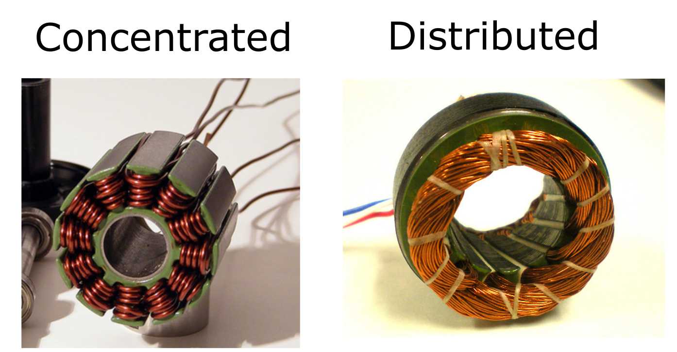
However, hobby grade brushless motors are almost universally constructed with concentrated windings. It is, therefore, a little surprising that they can produce a sinusoidal bEMF. The reason for a sinusoidal bEMF in the out-runner tested above is apparently related to its 12N14P configuration in combination with its doubly wound concentrated windings. I will explore this in more detail at some point in the future. Note that so far I have only measured 12N14P out-runner style motors and so you may see different results for motors with different slot/pole ratios or for in-runners.
BLDC or PMSM - Does it matter?
Useful torque is produced by an electric motor when you feed in a current waveform to each phase that perfectly opposes the a generated bEMF. Importantly, the shape of the waveform does not matter, so long as it exactly matches the bEMF waveform. For example, consider the torque produced by a PMSM and BLDC motor as seen by the figure below which were taken from James Mavey's excellent masters thesis.
 |
| Torque output vs current input for a PMSM (left) and a BLDC (right) motor |
When you sum up the current contributions from each phase for the sinusoidal waveform (PMSM) and for the trapezoidal waveform (BLDC) you see the same result; a perfect constant output current, and therefore a constant output torque. Also, in theory at least, both motors should be equally efficient. In reality, even if you could perfectly match the current to the bEMF, the rapid change in flux density seen by the stator in a BLDC motor due to the use of a trapezoidal waveform is likely to induce larger eddy current losses than a comparable sinusoidal PMSM.
The problems begin when you use a motor controller that outputs a current waveform which does not exactly match the bEMF of your motor. Most low-cost hobby grade motor controllers (ESC's) only output a 'six-step 120 degree' current waveform like that shown for the BLDC motor above. Therefore, if you use a PMSM with one of these ESC's it's torque output will be choppy, which creates audible noise, vibration, and will be quite inefficient. Instead, you would ideally use a motor controller which supports field oriented controlled (FOC) and that outputs a sinusoidal current waveform that more closely matches that of your motor.
Furthermore, the trapezoidal bEMF produced by a BLDC motor can vary quite a lot from motor to motor. This means that the current waveform produced by an ESC will never perfectly match the bEMF of a BLDC motor. This means that even if you match a BLDC motor with an ESC you will still have some amount of motor noise, vibration, and decreased efficiency. A PMSM has no such problem since ideally, ever motor produces the same sinusoidal bEMF.
For most hobby applications (e.g. small model planes, boats, and cars) using a PMSM with a conventional six step ESC won't cause any noticeable problems. However, for high-performance applications (e.g. multi-rotors used for cinematography, robotics and EV applications) the reduced noise, vibration and increased efficiency that comes from using a FOC motor controller with a PMSM may mean it's worth the extra investment.
Conclusion
If a motor produces a sinusoidal bEMF then its a PMSM and not a BLDC motor. A PMSM is best driven by a sinusoidal current as this reduces noise, vibration and improves efficiency.
In order to avoid confusion, going forward I will be simply referring to both BLDC and PMSM as brushless permanent magnet synchronous motors (PMSM).
In order to avoid confusion, going forward I will be simply referring to both BLDC and PMSM as brushless permanent magnet synchronous motors (PMSM).
If you have noticed any errors in the above article then please let me know.
I asked this on the Shane Colton FOC article you linked, but I'll ask you as well... can you explain why the goal of FOC is to align the stator coil field with the gap between rotor magnets (q axis), rather than keeping it just slightly ahead of the d axis?
ReplyDeleteSince strength of magnetic interaction decreases with distance, it seems like q axis alignment would be the weakest point. Obviously this is not the case, but I'd like to understand why.
Hi dekutree64
DeleteYou are correct when you say that the magnetic interaction (force produced on the rotor) decreases with distance from the rotor magnets. However, it is important to remember that we are only concerned with the forces tangential to the surface of the rotor. Any attraction between the rotor magnets and the stator vertically (pulling or pushing away from each other without turning the shaft) produces no torque on the rotor.
Consider the following three scenarios in which the stator has been replaced by another magnet:
1. https://drive.google.com/file/d/15IEpyXy3zTK9U8psNdCUQJUIydFiwTcm/view?usp=sharing
2. https://drive.google.com/file/d/1PcftQCUo2H-Saun2r8ufJtflaX1mhRca/view?usp=sharing
3. https://drive.google.com/file/d/10dCGg9o4L0FReRTc6Skp8tRl_0FNuL2l/view?usp=sharing
In 1 and 3 the motor would produce no torque since the magnets are 100% pulling or pushing away from each other while in 2 the maximum tangential force is produced. This is the q-axis located between the two magnets.
Thank you! That makes sense. You also get equal interaction with two rotor magnets this way. If you move the coil field toward one of them, you'd probably get a stronger tangential force with just that rotor magnet up to a point, but not enough to make up for the longer distance from the other.
DeleteAre you one of "those people" (look up the phrase) that believes that the torque produced by electric motors is as a result of the "bEMF"?
ReplyDeleteHi,
ReplyDeletethanks for these really helpful explanations. I was wondering about how to find out which type of motor controller I have. I used this one
https://www.yge.de/high-voltage-hv/ (type 90opto)
for a motor that is - considering the bEMF-function a PMSM. But I am not sure if the controller I used outputs a sinusoidal or a trapezoidal bEMF. I tried to measured the output of the controller, it seemed more like a trapezoidal output...but I am not sure what this means.
Maybe you have an idea how to interpret this.
Best regards
Sorry for the mistake:
DeleteThe controller doesn't output a bEMF, I wanted to say I am not sure about its output.
Hi
ReplyDeleteI see no mention of FOC or 'vector control' on the pdf provided by the website. If they did offer this feature its a big selling point and so it would most likely be listed.
https://www.yge.de/wp-content/uploads/2018/08/YGE-90-120HVT-Opto-eng-1.pdf
This, along with the comments in the pdf about 'automatic 6 step control' leads me to believe this controller does not use FOC and so its output will be trapezoidal.
To know for sure you could just contact the company and ask.
Cheers,
Richard
Appreciate your blog posts on here, but it would be interesting to know how to analytically design a "BLDC" motor with sinusoidal back emf. In practice, I would assume that even the hobby motor you empirically measured is not exactly sinusoidal, but approximates a sinusoid based on the relative positions of all the magnets near the stator slots.
ReplyDelete