However, it is also well known that the longer you make a permanent magnet, the larger the flux density at its surface. This raises an important question: Are long magnets and a large flux gap better than short magnets and a small flux gap when it comes to producing the most torque?
 |
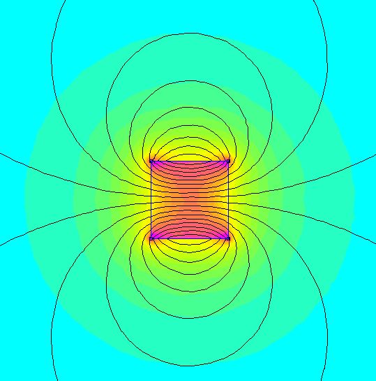
| Small flux gap and magnets on the left, large magnets and flux gap on the right. |
The short answer:
For a 'hobby grade' out-runner electric motor the optimal magnet length will depend on your exact motor design, but in general, it will likely be around 1 to 4mm in length. Shorter magnets see a rapid fall off in their flux contribution to the airgap while longer magnets increase the magnetic reluctance of the magnetic circuit, reducing the stator contribution. Very long magnets will also cause the stator and rotor back iron to saturate which reduces performance.Read on if you would like a more detailed understanding.
Permanent magnet self demagnetisation
Below are four magnets modelled in FEMM with a length of 1, 2, 4 and 8 mm


Despite each magnet being made of the same material there is a clear difference in the flux density present at the surface poles. The reason for this effect is that shorter magnets have a higher demagnetisation factor in that direction. The demagnetisation factor reduces the B field inside the magnet and is dependent upon the magnet geometry. The concept of a demagnetisation factor also applies to soft magnetic materials, not just permanent magnets. Long magnets will have a lower demagnetisation factor than shorter magnets. Unfortunately, there is no simple equation that can be used to describe the demagnetisation factor for something as basic as a cube. However, there is a simple relationship for an ellipsoid. Note that if you have a magnetic circuit that makes a closed circuit then the demagnetisation factor is zero but there are also no magnetic poles.
If we draw a line projecting out from the surface pole of each magnet and measure the flux density at each point we get the following plot.


As the magnet is made longer, and its demagnetisation factor in that direction decreases, the field produced at the surface poles would eventually approach that of the magnets remanent magnetisation. The plot above will look quite different if the same magnet was instead placed into the rotor of a motor since you then also have high magnetic permeability material in the stator and rotor helping guide the flux from the magnet, reducing its demagnetisation factor. However the overall concept remains the same.
Effect of magnet length on the torque produced by a simple motor
As in the previous post, we can use a simple model of a motor to test how different magnet lengths impact the torque produced for a fixed winding current. Below are four different scenarios. Each motor has a gap between the stator and the magnets of 0.5 mm. Therefore, the total flux gap is given by the magnet length + 0.5 mm.
 |
| 1 mm rotor magnet |
 |
| 2 mm rotor magnet |
 |
| 4 mm rotor magnet |
 |
| 8 mm rotor magnet |
We can see a few things right away. First, the flux density in the rotor 'back iron' increases considerably as you make the magnets longer to the point that the back iron begins to saturate. This can also be seen in the stator teeth. Secondly, we can see that more flux escapes the rotor and fringes into the surrounding air. This is due to the saturation of the back iron.
The flux density in the flux gap is plotted below with different length magnets. The flux contribution from only the stator windings was estimated by removing the magnets and simulating the motor. The same was done for the flux density contribution for the magnets, this time with the stator winding current set to zero.

It is clear that as you make the magnets longer the flux contribution from the stator becomes smaller due to the increase in the flux gap size. On the other hand, the flux density contribution from the magnets increases as they are made longer. Based on this plot we would expect that the torque will continue to rise as the magnets are increased in length. However, when the rotor torque is plotted with respect to the magnet length we can see that maximum torque is reached for magnets that are about 4 mm long. Further increasing the magnet length sees the torque slowly fall off.

This fall off in torque for magnets longer than about 4 mm is likely due to the stator core and rotor back iron beginning to saturate. Perhaps more interestingly is if we plot the specific torque density (torque per unit volume) and gravimetric torque density (torque per unit mass).

When the magnets are made longer they are adding mass and volume to the entire motor while the torque gradually decreases. Therefore, there is a sharp fall off in the specific torque density for magnets longer than about 2 mm. Note that in the above example only the magnet length was changed. If more than one parameter was refined for, such as the thickness of the back iron, then the results will differ from those above.
In addition to just the torque output there are many other factors which need to be considered when you change the length of the magnets contained in a motor. A few that come to mind may include:
- Core losses are likely to increase when magnet length is increased as the stator and rotor iron is operating closer to saturation. Stray flux from the magnets may also cause more eddy current losses in the windings.
- Magnets are easily the most expensive part of a hobby grade electric motor. Therefore, motor cost will increase considerably if you were to use longer magnets, even if a redesigned motor did see a slight increase in torque with magnet length.
- Increasing the magnet length will add more mass to the rotor which increases its moment of inertia, reducing the dynamic response time of the motor.
- Cogging torque generated by the salient poles of the stator will likely be much worse with more powerful magnets
- There are many different grades of magnetic materiel. Using more or less powerful magnets would likely change the optimum magnet length.
Conclusion
Increasing the length of the permanent magnets used in a 'BLDC' (PMSM) motor will increase the torque produced only up to a point. The optimum magnet length will depend on many factors, but as a general rule of thumb, this length will be between 1 and 4 mm for 'hobby grade' out-runner electric motors constructed with back iron in the rotor. Further increasing the magnet length will only reduce the motor performance and increase the motors production costs.
If you have noticed any errors in the above article then please let me know. If you would like to play around with any of the models shown in this post in FEMM you can find the files hosted here. This tutorial gives you enough information to get started if you have never used FEMM before.
Thanks for making this blog; your clear exposition of these subjects has helped me move my own understanding forward. However, isnt varying the magnet thickness alone a bit of a strawman? For starters, the original iron backing seems well dimension wrt saturation; and with the extra PM material it becomes an obvious bottleneck. Of course the same goes for many other components that could be adjusted, subtly or not so subtly. Of course it would make for a much more complex analysis, but the effect of magnet-length, while optimizing all other parameters to the new conditions, would be the more interesting question to answer.
ReplyDeleteI think the simplest argument against more magnet lies in the fact that relative to its magnetised closed loop state, it is an extremely magnetically hard material, but with a finite saturation flux. For a loop with a given reluctance, adding more neodymium quickly takes the flux up to where the neodymium wants it to be, with equally quickly diminishing returns after that.
Hi EH
ReplyDeleteThanks for your feedback. I agree that just increasing the magnet thickness without optimising other parameters will not lead to an ideal solution. At some point in the future I will explore this in more detail by parametrically adjusting the back iron thickness, tooth thickness etc. I suspect that the ‘ideal’ motor shape for a given magnet thickness will vary a lot depending on the motor application. i.e. for maximum toque per volume with liquid cooling the copper winding area could be sacrificed in favour of wider stator teeth while for maximum torque per dollar of material we may see something much closer to existing motor designs.
Cheers,
Richard.