Showing posts with label rotor. Show all posts

Sunday, January 27, 2019

Selecting the best pole and slot combination for a BLDC (PMSM) motor with concentrated windings

The full spreadsheet used in this post is available for download. To modify the sheet just choose the 'Make a copy option' from the drop-down file menu.

Introduction 

Concentrated windings have a single coil per tooth and are commonly used on 'hobbyist' style BLDC (PMSM) out-runner motors.

A key advantage of concentrated windings is that they can be quickly and cheaply wound by machine as seen in the video below.


Even motors with very thick conductors can be wound by machine.


Other advantages include short end turns, which do not contribute torque to the motor and only increase the winding resistance, and space for effective air cooling. A major drawback of concentrated windings is that without careful consideration of the stator slot number and rotor pole number the performance of the motor will be poor.


This post will examine the advantages and disadvantages of different slot and pole combinations. The information is based off the paper 'Distribution, coil-span and winding factors for PM machines with concentrated windings' by S.E Skaar et al. and the book 'Design of Brushless Permanent-magnet Machines' by J. R. Hendershot and T. Miller. See the 'recommended reading' list above for more information on this book. The emotor.com glossary page is also useful for reference.

The winding factor

An electric motors 'winding factor' (not to be confused with its copper fill factor) is a number between 0 and 1 which represents the fraction of the armature current which is used to produce torque.

From emotor.com's glossary page the winding factor is defined as the following:
The winding factor for a specific winding expresses the ratio of flux linked by that winding compared to flux that would have been linked by a single-layer full-pitch non-skewed integer-slot winding with the same number of turns and one single slot per pole per phase. The torque of an electric motor is proportional to the fundamental winding factor.
Despite being so fundamental, the calculation of the winding factor is not often discussed in textbooks. I found that the paper mentioned above has the easiest to follow description, although I had to rely on the emotor.com description of an unbalanced winding as the solution provided in the paper appears to not cover all scenarios.

I will not be going into detail about the calculation of the winding factor. However, you can find the spreadsheet used to calculate the values shown in this post here. This spreadsheet includes up to 108 slots and 70 poles and is easily extended further where needed.

The winding factor for a 3 phase machine with a non-skewed rotor can be seen listed in the table below where the top row is the number of poles and the left-hand column is the number slots. Since this is a three-phase machine the number of slots increases by three and since a magnet has two poles (a pole pair) the pole number increases by two.


It can be seen that some slot and pole combination have a winding factor of one while others are approaching zero, or even negative. However, not all of these slot and pole combinations can be used as is described below.

1. Exclude windings where q < 0.25

The slot to pole ratio with consideration for the number of phases is designated by the variable q. If q is less than 0.25 then the arc covered by a rotor pole is now less than half a stator tooth. This results in multiple north and south magnet poles interacting with each stator tooth and so the torque generated by the motor is reduced. Therefore, q values of less than 0.25 are generally not considered feasible and can be eliminated. The images below were created with this winding layout tool. Note that in reality, the gap between each stator tooth would be much smaller.

Example winding layouts that give a q value that is not considered feasible.

The calculated q-values for different slot and plot combinations.

The winding factor of each slot and pole combination with those combinations that give q<0.25 removed.

2. Exclude windings where q > 0.5

Alternatively, if q is greater than 0.5 then it no longer makes sense to use a concentrated winding as a single rotor pole will span over multiple teeth. Instead, a distributed windings would be used. Therefore, these combinations can also be excluded for our purposes.


3. Exclude windings where Ns = Nm

If the number of slots (Ns) is equal to the number of poles (Nm) then the motor will produce large cogging torque and will no longer be self stating. This combination can therefore also be eliminated.


4. Removal of unbalanced windings and motors without symmetry

A motor with balanced windings will have the same number of coils for each phase per repeating segment of the motor. A motor must have balanced windings for operation. More information here. 


Also, it is ideal to have a motor that has a symmetry of at least 2 (i.e. the motor has two repeating sections) as this helps avoid unbalanced radial forces and noisy operation. In other words, a motor without any symmetry will produce its torque on only one side of the rotor. If a motor has a symmetry of two then its torque will be produced on opposite sides of the rotor, balancing the forces.

The slot and pole combinations that produced unbalanced windings and no symmetry can, therefore, be eliminated.


Based on the table above it can be seen that 12s10p and 12s14p are attractive combinations. This explains why these slot and pole combinations are so popular for 'hobbyist' out-runner electric motors.

5. Consideration of cogging torque

In addition to the winding factor, cogging torque is also an important consideration. Cogging torque creates vibration and noise during operation and acts to disturb the motor away from its desired position when used in servo applications. The cogging torque frequency is also closely correlated with the production of rotor losses both with and without current supplied to the armature.

The cogging torque frequency is given by the least common multiple (LCM) of the stator slots and the rotor poles. The figure below displays the possible slot and pole combinations with the winding factor replaced with the cogging torque frequency. 


Selecting as high a cogging frequency as possible is desirable as it reduces the amplitude of the cogging torque. With this in mind, 24s22p would be an attractive option with its 264 cogging steps per rotation and 0.949 winding factor as opposed to only 84 cogging steps per rotation for 12s14p.

6. Higher order harmonics

So far we have only been considering the fundamental winding factor. However, different slot and pole combinations also affect the winding space harmonics. This topic will be covered in more detail in a future post once I have a better understanding of the topic.

7. Additional considerations

From the last two tables above its easy to conclude that a 24s22p motor is 'better' than a 12s14p motor since it has both a higher winding factor and a higher cogging frequency. However, there are other factors that also need to be considered.

7. 1 Maximum electrical frequency

The electrical frequency (current sine-wave supplied to each phase) scales linearly with the number of pole pairs (Nm/2) of a motor. Therefore, doubling the pole count of a motor will increase its core losses by a factor of four since it scales with the square of the electrical frequency. Doubling the pole count will also double the back EMF produced and so twice the required voltage will be needed to drive the motor at the same RPM. However, rewinding of the motor with a lower number of conductors per tooth can be used to offset this increase in the back EMF and will not impact the efficiency of the motor. In addition, reducing the lamination thickness will help minimise eddy current losses, which scale with the square of the lamination thickness. See this spreadsheet for more details. At the extreme, the switching frequency of the motor controller used to drive the motor may also need to be increased in order to maintain a good approximation of a sine wave. This will incur additional dead time losses in the motor controller. 

The electrical frequency required to operate the motor at 10,000 RPM is shown below.


7. 2 Mechanical winding considerations

Trying to squeeze more slots into a small motor is not always possible. Increasing the number of slots while keeping the motor diameter the same typically means that multiple smaller conductors must be used in order to bend around the tighter radii and make use of the available space. Smaller conductors have a larger fraction of their total cross section taken up by insulation and so the copper fill factor of the motor can be reduced even if the winding factor is increased. A lower copper fill factor means a higher current density in the winding and so higher I^2R losses.

7. 3 Cooling considerations

Effective cooling is critical for a high power density electric motor. Having a large number of slots and small conductors may congest the air flow path and reduce air cooling effectiveness. This, in combination with higher core losses due to an increase in the electrical frequency, can reduce the power density of a motor.

7. 4 Tooth-tip leakage

Squeezing more slots into a motor may also require that the gaps between the teeth be reduced. Reducing the size of this gap can allow some flux to jump (or zig-zag) from one tooth to the next, reducing the effective torque produced by the motor.

7. 5 Rotor skewing

If you plan on skewing your motor in an effort to reduce its cogging torque then it is important that the required skew does not lower the winding factor too much. The reduction in the winding factor is given by the skew factor discussed here. This topic will be covered in more detail in a future post.

7. 6 Reduced rotor and stator back-iron (yoke) mass

Increasing the pole and slot count of an electric motor has the advantage of reducing the flux density in the back-iron. This is because the higher number of stator slots and rotor poles means that flux does not need to travel as far around the stator or rotor to make a closed magnetic path. For every doubling of the pole or slot number, the flux density is halved and so the thickness, and therefore mass, of the back-iron can also be halved. This acts to increase the power density of the motor. 

For example, Siemens appears to have increased the gravimetric torque density (torque per unit mass) by 50% for their 260 kW light aircraft electric motor by increasing its pole and slot count from an already high 36s30p to 72s60p. Note that this assumption is based solely on the images from their promotional material.

Conclusion

The tables above provide guidance when selecting the number of slots and poles for a BLDC (PMSM) motor with concentrated windings. If the diameter of your motor is less than approximately 60 mm and if your maximum RPM is less than 10,000 then 10s14p or 12s14p may be a good choice. For larger diameter and/or motors that rotate more slowly a higher slot and pole count can be used, such as 24s26p with a reduced number of turns per tooth and thinner Fe-Si laminations. Higher pole count motors will have a higher electrical frequency, increasing losses, but will also have a lower mass since a reduced back-iron thickness can be used while also having a smaller cogging torque amplitude.

Thursday, December 27, 2018

Understanding BLDC (PMSM) electric motor constants - Optimal magnet length for high torque density

In the last post it was shown that the torque density of a motor can be improved by making the flux gap as small as possible. It was also seen that the rotor magnets are considered part of the flux gap. Therefore, it would appear that an ideal motor will always have rotor magnets that are as thin as possible.

However, it is also well known that the longer you make a permanent magnet, the larger the flux density at its surface. This raises an important question: Are long magnets and a large flux gap better than short magnets and a small flux gap when it comes to producing the most torque?
Small flux gap and magnets on the left, large magnets and flux gap on the right.

The short answer: 

For a 'hobby grade' out-runner electric motor the optimal magnet length will depend on your exact motor design, but in general, it will likely be around 1 to 4mm in length. Shorter magnets see a rapid fall off in their flux contribution to the airgap while longer magnets increase the magnetic reluctance of the magnetic circuit, reducing the stator contribution. Very long magnets will also cause the stator and rotor back iron to saturate which reduces performance.

Read on if you would like a more detailed understanding.

Permanent magnet self demagnetisation

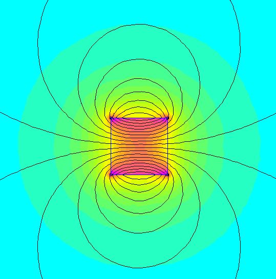
Below are four magnets  modelled in FEMM with a length of 1, 2, 4 and 8 mm 


Despite each magnet being made of the same material there is a clear difference in the flux density present at the surface poles. The reason for this effect is that shorter magnets have a higher demagnetisation factor in that direction. The demagnetisation factor reduces the B field inside the magnet and is dependent upon the magnet geometry. The concept of a demagnetisation factor also applies to soft magnetic materials, not just permanent magnets. Long magnets will have a lower demagnetisation factor than shorter magnets. Unfortunately, there is no simple equation that can be used to describe the demagnetisation factor for something as basic as a cube. However, there is a simple relationship for an ellipsoid. Note that if you have a magnetic circuit that makes a closed circuit then the demagnetisation factor is zero but there are also no magnetic poles.

If we draw a line projecting out from the surface pole of each magnet and measure the flux density at each point we get the following plot.


Here we can see that the flux density in air for the 8 x 8 mm magnet at a distance of ~ 10 mm is the same as the surface (0 mm distance) for the 1 x 8 mm. This trend of increasing flux density with magnet length does not continue forever. The flux density in air at a distance of 0.5 mm from the surface of the magnets is plotted vs magnet length below.


As the magnet is made longer, and its demagnetisation factor in that direction decreases, the field produced at the surface poles would eventually approach that of the magnets remanent magnetisation. The plot above will look quite different if the same magnet was instead placed into the rotor of a motor since you then also have high magnetic permeability material in the stator and rotor helping guide the flux from the magnet, reducing its demagnetisation factor. However the overall concept remains the same.

Effect of magnet length on the torque produced by a simple motor

As in the previous post, we can use a simple model of a motor to test how different magnet lengths impact the torque produced for a fixed winding current. Below are four different scenarios. Each motor has a gap between the stator and the magnets of 0.5 mm. Therefore, the total flux gap is given by the magnet length + 0.5 mm. 

1 mm rotor magnet

2 mm rotor magnet

4 mm rotor magnet

8 mm rotor magnet
We can see a few things right away. First, the flux density in the rotor 'back iron' increases considerably as you make the magnets longer to the point that the back iron begins to saturate. This can also be seen in the stator teeth. Secondly, we can see that more flux escapes the rotor and fringes into the surrounding air. This is due to the saturation of the back iron. 

The flux density in the flux gap is plotted below with different length magnets. The flux contribution from only the stator windings was estimated by removing the magnets and simulating the motor. The same was done for the flux density contribution for the magnets, this time with the stator winding current set to zero.


It is clear that as you make the magnets longer the flux contribution from the stator becomes smaller due to the increase in the flux gap size. On the other hand, the flux density contribution from the magnets increases as they are made longer. Based on this plot we would expect that the torque will continue to rise as the magnets are increased in length. However, when the rotor torque is plotted with respect to the magnet length we can see that maximum torque is reached for magnets that are about 4 mm long. Further increasing the magnet length sees the torque slowly fall off.


This fall off in torque for magnets longer than about 4 mm is likely due to the stator core and rotor back iron beginning to saturate. Perhaps more interestingly is if we plot the specific torque density (torque per unit volume) and gravimetric torque density (torque per unit mass).  

When the magnets are made longer they are adding mass and volume to the entire motor while the torque gradually decreases. Therefore, there is a sharp fall off in the specific torque density for magnets longer than about 2 mm. Note that in the above example only the magnet length was changed. If more than one parameter was refined for, such as the thickness of the back iron, then the results will differ from those above.

In addition to just the torque output there are many other factors which need to be considered when you change the length of the magnets contained in a motor. A few that come to mind may include:
  • Core losses are likely to increase when magnet length is increased as the stator and rotor iron is operating closer to saturation. Stray flux from the magnets may also cause more eddy current losses in the windings.
  • Magnets are easily the most expensive part of a hobby grade electric motor. Therefore, motor cost will increase considerably if you were to use longer magnets, even if a redesigned motor did see a slight increase in torque with magnet length.
  • Increasing the magnet length will add more mass to the rotor which increases its moment of inertia, reducing the dynamic response time of the motor.
  • Cogging torque generated by the salient poles of the stator will likely be much worse with more powerful magnets
  • There are many different grades of magnetic materiel. Using more or less powerful magnets would likely change the optimum magnet length.

Conclusion

Increasing the length of the permanent magnets used in a 'BLDC' (PMSM) motor will increase the torque produced only up to a point. The optimum magnet length will depend on many factors, but as a general rule of thumb, this length will be between 1 and 4 mm for 'hobby grade' out-runner electric motors constructed with back iron in the rotor. Further increasing the magnet length will only reduce the motor performance and increase the motors production costs.

If you have noticed any errors in the above article then please let me know. If you would like to play around with any of the models shown in this post in FEMM you can find the files hosted here. This tutorial gives you enough information to get started if you have never used FEMM before.

Wednesday, December 26, 2018

Understanding BLDC (PMSM) electric motor constants - Optimal flux gap for high torque density

For many weight sensitive applications in robotics, it is desirable to have high torque density actuators. It is also often desirable to have relatively low gear ratios as this improves un-sensored output torque accuracy and helps to minimise rotational inertia, which improves angular acceleration. This is the basis of Ben Katz low-cost modular actuator design. There is, therefore, a need for electric motors with as high a gravimetric torque density (torque per unit mass) as possible.

Despite this, I have so far been unable to find much information online in the 'hobbyist community' (i.e. non-academic) about which aspects of an electric motor are important for torque density and how they can be optimised. Therefore, for the next series of posts I will be using FEMM and a simple motor model to try and develop a working understanding of how different motor parameters (e.g. flux gap size, magnet length, stator tooth shape, slot and pole number etc.) impact the torque density of a brushless permanent magnet synchronous motor.

Let's get started.

The flux gap

The flux gap is the distance between the high magnetic permeability material in the stator (stator 'iron') and the corresponding high magnetic permeability material in the rotor (rotor 'back iron'). This material is normally made of thin laminations of Fe-Si steel.

It is well known that, in general, the flux gap should be as small as possible.


It is important to note here that the flux gap includes the magnets. Rare earth magnets (magnetised or un-magnetised) have a magnetic permeability essentially the same as air. Therefore, from the stators perspective, a magnet is no different than air and should be included as part of the flux gap. 

Let's start by considering two simple magnetic circuits simulated in FEMM; one with a 1 mm flux gap and one with a 4 mm flux gap.

1 mm flux gap core
4 mm flux gap
The magnetic circuit consists of a ring of soft iron (literally pure annealed iron), copper windings represented by the green rectangles (2A, 250 turns) and an air gap in the ring. The flux density (unit of Tesla) is represented by how close the lines of flux are together and by the colour, with red being the highest density and blue being the lowest. The flux density in the ring with the small flux gap is clearly the largest. This ring also has the least amount of flux 'leaking' out into the surrounding air.

The reason for this difference is that an air gap increases the magnetic reluctance of the circuit. Magnetic reluctance is to flux in a magnetic circuit what resistance is to a current in an electric circuit. Therefore, the magnetic flux in the circuit is dependent upon the total magnetic reluctance and the applied magneto-motive force (turns times current) just as an electrical current is dependent upon the total resistance in an electric circuit and the applied voltage. For a nice overview of the concept check out Ben Krasnow's video on the topic.

Let's look more closely at how the flux changes over the flux gap itself. We can do this by drawing a line over the flux gap and measuring the flux density at each point on the line.

The 4 mm flux gap and line which we will measure flux density


Doing this for both the 1 mm and 4 mm flux gap it is clear that the flux in the middle of each gap remains constant. It can also be seen that the flux is four times smaller in the 4 mm flux gap than the 1 mm flux gap. Therefore, in order to produce the same flux density in the 4 mm gap, we would need to either add four times as many windings at the same current or alternatively, keep the same number of windings and add four times as much current. This concept can also be applied to electric motors and explains why engineers generally do everything they can to keep the flux gap as small as possible.

The flux density in the flux gap can be approximated using the following equation:

`B=\frac{\mu_{0}NI}{g}`

where B is the flux density (Tesla), `mu_{0}` is the magnetic permeability of free space `(4\pi\times10^{-7})`, N is the number of turns of wire, I is the current (Ampere) and g is the flux gap (meters). Plotting B vs g we see the following:


This equation assumes that the reluctance of the iron core is negligible. This is a safe assumption in this example as reluctance of the Fe core is around `10^{-7}` times smaller than the reluctance of the flux gap and so can be disregarded. However, if your core is close to saturation, as would be the case if you reduce the flux gap to zero, then this will not always be the case. Also, this equation can only be used for a constant cross-section like that of the 'racetrack' core shown above, but does provide a good starting point for cores of other shapes. For best results a FEA package like FEMM (its free!) will give the best approximation.

Unlike the simple magnetic circuits shown above, the flux gap problem is made more complicated for BLDC motors for a few reasons:
  1. There are multiple flux gaps. The stator flux must travel across to the rotor and back again and can do so at multiple points.
  2. The magnetic permeability, and hence the magnetic reluctance, of the ferromagnetic stator and rotor back iron, is not constant but instead depends on the total amount of flux in that region.
Note that simply embedding the magnets in the rotor back iron does not eliminate the flux gap, it only moves it further back into the rotor. Embedded rotor magnets do have their own advantages (improved field weakening performance, control over reluctance torque) but they are topics for another day.

Effect of flux gap size on torque for a simple motor

In order to explore the impact of the flux gap size on something more closely resembling a real  motor I have simulated a 6 slot, 8 pole 'out runner'. The motor was sketched in F360 and exported as a dxf file for use in FEMM. It has a stator diameter of 57 mm and a rotor length (into screen) of 10 mm. This motor has three phases which are wound with concentrated windings (double layered) as ABCABC. A current of 50A is supplied on phase A, and -25A is supplied on phase B and C so that all of the flux is directed on the Q-axis where it will produce the most torque.

The motor is simulated with a fixed current at 90 degree
Shane Colton's blog post on field orientation has a good rundown on the q-axis and d-axis argument.  In short, the phase with the most current on it (phase A) is 90 electrical degrees ahead (q-axis) of the direct flux of the magnets (d-axis) where it will produce the most torque per amp. If the rotor was rotating then so too would the magnetic field generated in the stator so that the torque remains constant and proportional to the current.


Flux density due to the stator windings only (magnets removed)
However, in this simulation, both the current and rotor position are fixed and we are instead only solving for the flux density generated in the air gap by the stator windings and the magnets.
In the simulation seen below the flux is seen to be concentrated in the high magnetic permeability stator teeth and in the back iron of the rotor. This flux almost exclusively crosses at the flux gap.

1 mm flux gap
For comparison, a motor with a 3mm flux gap is shown below. Here we can see that the total flux density in the stator teeth and back iron is greatly reduced due to the increased magnetic reluctance in the magnetic circuit. This decrease is also seen in the flux gap where the magnets are located.

3 mm flux gap
If you would like to play around with these models in FEMM you can find the files hosted here. This tutorial gives you enough information to get started if you have never used FEMM before.

Using FEMM it is also possible to estimate the static torque that this 10 mm long rotor would produce. The torque and flux density within the flux gap with respect to the flux gap size is shown below.

We can see two things quite clearly: i) the torque produced by the motor is dependent upon the flux density in the air gap and ii) the torque falls off asymptotically as the flux gap size is increased. Note that in this example we are increasing the diameter of the rotor to increase the flux gap. Since motor torque increases with the square of the flux gap diameter the fall off in torque would be much steeper if we were to instead decrease the size of the stator to increase the flux gap.

From the above discussion it is clear that, in general, we want to have as small a flux gap as physically possible so as to increase the motors torque output and, therefore, it's motor constant. However, aside from needing to consider manufacturing tolerances, we also need to consider the thickness of the magnets. In general, if you make the rotor magnets longer then the flux density at their poles is also increased. This will act to increase the torque output of your motor.

The impact of magnet length to motor torque will, therefore, be the topic of the next post.

Conclusion

Increasing the size of the flux gap for a motor will increase the magnetic reluctance in the magnetic circuit which reduces the flux density in the air gap. The torque generated by a motor is proportional to the flux in the air gap. Therefore, increasing the size of the flux gap will reduce the torque generated by a motor for a fixed winding current, which reduces the overall motor constant. 

Equations were produced in this post with the help of arachnoid.com and are based on those found in the book Electric Motors and Drives: Fundamentals, types and applications by Austin Hughes. If you have noticed any errors in the above article then please let me know.